An Earth Resistivity Test is a scientific field investigation that measures the electrical resistance of soil at a project site. It is the foundation of any reliable earthing or grounding system design. When electrical current passes through the ground, the soil's ability to conduct or resist that current directly determines how safely and efficiently an earthing system will perform.
For substations, solar power plants, telecom towers, industrial facilities, airports, and data centres, a properly designed earthing system is not optional — it is a safety and regulatory requirement. Incorrect or absent soil resistivity data leads to under-designed earthing grids, equipment damage, personnel hazards, and costly rework.
Quick Definition: Earth Resistivity (measured in Ohm-metres, Ω·m) is the measure of how strongly a given volume of soil opposes the flow of electric current. Lower resistivity = better conductivity = easier to achieve safe earthing. Professional soil resistivity testing ensures your grounding system is designed on real site data, not assumptions.
An Earth Resistivity Test — also known as a soil resistivity test, ground resistivity test, or electrical earth resistivity measurement — is a geophysical field procedure that determines the resistivity of subsurface soil layers using electrical current injection and voltage measurement.
The measurement is based on Ohm's Law and the principle that soil acts as a natural electrical conductor. The resistivity value depends on soil composition, moisture content, mineral salts, temperature, and depth. Sandy, dry, or rocky soils show high resistivity, while clay-rich, moist, or saline soils show low resistivity.
A soil electrical resistivity analysis gives engineers the data required to:
- Design efficient and code-compliant earthing grids
- Select the correct electrode type, depth, and spacing
- Calculate expected earth fault current dissipation
- Prevent equipment damage due to ground potential rise
- Comply with IS 3043, IEEE 80, and IEC 60364 standards
Electrical safety depends entirely on how well your earthing system performs. Without an accurate earthing resistivity test, engineers are designing blind. Here is why soil resistivity testing is non-negotiable:
Solar Power Plants
Earthing grid design for DC arrays, inverters, and AC switchgear requires site-specific soil resistivity data to prevent transient overvoltages and equipment failure.
Electrical Substations
Substation earthing grids are life-safety systems. Resistivity testing for substations is mandatory before any grid design can begin.
Industrial Facilities
Heavy manufacturing, chemical plants, and oil & gas installations require low-resistance earthing due to high fault currents and explosive atmosphere risks.
Telecom & Transmission Towers
Tower base earthing must meet resistance thresholds to protect against lightning strikes and induced voltages on communication lines.
Airports & Government Infrastructure
Large-scale projects with stringent safety codes require comprehensive soil resistivity surveys across multiple testing points.
Railway Infrastructure
Traction substation earthing, signalling system grounding, and overhead equipment structures all require validated ground resistivity data.
Mining & Heavy Industrial Facilities
Remote mining sites with rocky or dry soil present high-resistivity challenges requiring specialised earthing design based on accurate test data.
Data Centres
Sensitive electronic infrastructure requires ultra-low resistance earthing. Soil resistivity measurement guides the electrode density needed.
Commercial Buildings & Residential Developments
IS 3043-compliant earthing for LT and HT installations requires soil resistivity testing to size electrodes correctly.
Methods Used in Earth Resistivity Testing
Field-based soil resistivity measurement methods use different electrode configurations to probe various depths of the soil profile. The three most widely used techniques are:
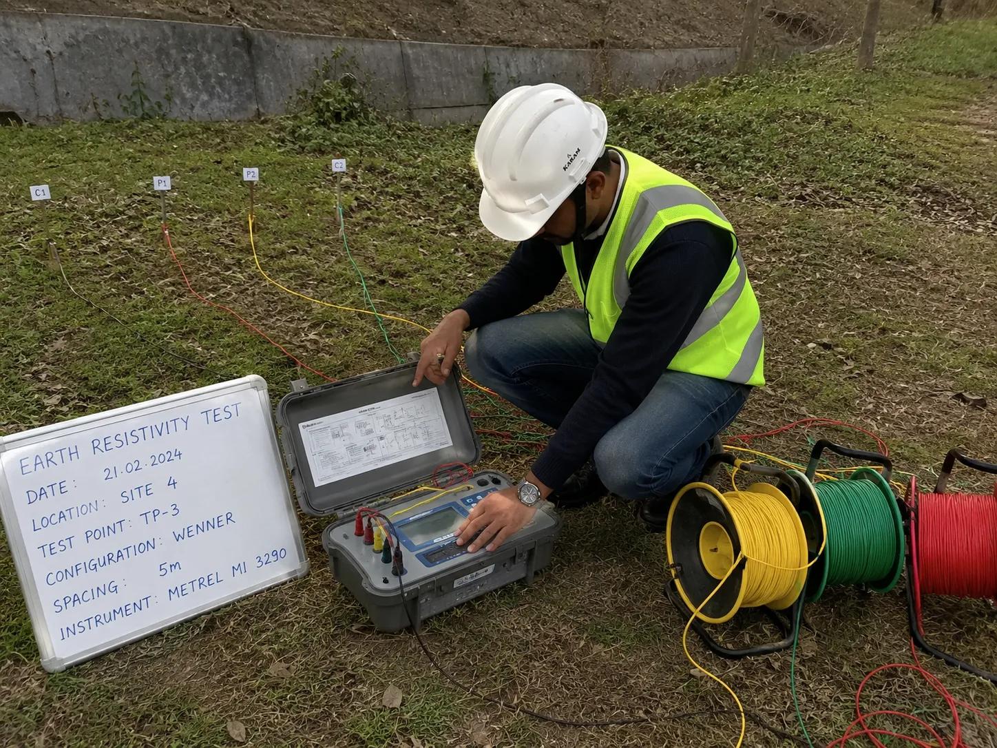
Wenner Four-Pin Method
The Wenner method is the most widely used standard for earth resistivity measurement in India and globally. Four equally spaced metal electrodes are driven into the ground in a straight line. Current is passed through the two outer electrodes, and the voltage drop is measured across the two inner electrodes.
Resistivity (ρ) is calculated as: ρ = 2π a R, where 'a' is the electrode spacing and 'R' is the measured resistance. By varying the spacing 'a', engineers can map resistivity at different depths, giving a full vertical soil resistivity profile.
- High accuracy over large survey areas
- Suitable for substations, solar plants, and industrial sites
- Standard method per IEEE 80 and IS 3043
Schlumberger Method
In the Schlumberger array, the outer current electrodes are spaced much wider apart than the inner potential electrodes. This configuration is particularly effective for deep resistivity profiling, making it well-suited for large substations and transmission line tower foundations where deep soil layers influence earthing performance.
Driven Rod Method
The driven rod (or fall-of-potential) method measures the resistance of an already installed earth electrode. It is primarily used for verification testing of completed earthing installations — confirming that the as-built system meets the design target resistance values before a facility is energised.
Bhoojal Survey deploys advanced field instrumentation to ensure precise and reliable soil resistivity survey data.
Our standard equipment suite includes:
- Digital Soil Resistivity Meter (4-pin Wenner/Schlumberger capable)
- Stainless-steel drive electrodes and insulated test cables
- GPS mapping tools for accurate electrode position recording
- Data logging and field tablet systems for real-time data capture
- Geophysical resistivity survey instruments for multi-layer profiling
- SSRMPATS Instrument, GER DETECT, and PQWT for hydrogeological and geophysical surveys
Our team also conducts hydrogeological surveys using SSRMPATS Instrument, GER DETECT, and PQWT at site for open well and borewell location identification — combining advanced groundwater and geophysical survey solutions with scientific site investigation and resistivity analysis for comprehensive infrastructure project support.
Understanding what influences soil resistivity helps engineers anticipate challenges and design robust earthing systems. Key factors include:
Soil Moisture Content: Water dramatically reduces resistivity. Dry soils can have resistivity 10–100x higher than saturated soils of the same type.
Soil Composition & Minerals: Clay and loam have low resistivity. Sand, gravel, and rock have high resistivity. Mineral salt content significantly increases conductivity.
Temperature: Resistivity increases as soil temperature drops. This is critical for projects in high-altitude or cold-climate zones.
Groundwater Depth: Sites with shallow groundwater tend to have lower resistivity at depth — advantageous for achieving low earthing resistance.
Seasonal Variation: Resistivity changes between wet and dry seasons. Testing during the driest period gives conservative worst-case design values.
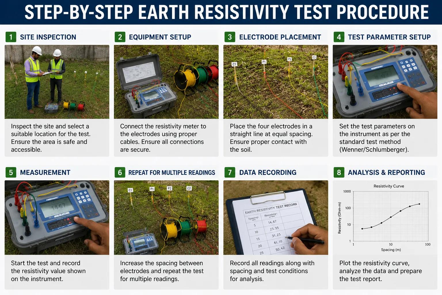
Step-by-Step Earth Resistivity Test Procedure
Bhoojal Survey follows a rigorous, systematic workflow for every electrical earth resistivity test engagement:
1. Site Inspection & Briefing
Engineers visit the project site to assess terrain, access conditions, existing utilities, and scope of testing required.
2. Survey Planning & Grid Layout
Based on site drawings and project specifications, the test grid, electrode spacing intervals, and traverse lines are planned and marked.
3. Electrode Placement
Electrodes are driven to the specified depth at measured intervals along each traverse line, with GPS coordinates recorded.
4. Current Injection & Voltage Measurement
The resistivity instrument injects a known AC current through the outer electrodes and measures the resulting voltage drop across the inner electrodes.
5. Field Data Collection
Resistance readings are recorded systematically across all spacing intervals and traverse positions. Multiple readings are taken for statistical accuracy.
6. Resistivity Calculation
Apparent resistivity values are calculated using the Wenner formula (ρ = 2πaR) for each electrode spacing.
7. Data Interpretation & Soil Layer Modelling
The resistivity-depth profile is analysed. Multi-layer soil models are developed to identify resistivity of each soil horizon.
8. Technical Report Preparation
A comprehensive report is prepared including all field data, resistivity profiles, soil layer models, and graphical representations.
9. Engineering Recommendations
The report includes specific recommendations for earthing electrode type, depth, spacing, soil treatment requirements, and expected system resistance.
Benefits of Professional Earth Resistivity Testing Services
- Accurate Earthing System Design: Site-specific resistivity data eliminates guesswork, ensuring your earthing grid meets the required fault current dissipation specifications.
- Reduced Electrical Infrastructure Risk: Properly designed earthing systems prevent ground potential rise events that can damage equipment and injure personnel.
- Cost Savings in Project Development: Correct first-time design avoids expensive post-installation modifications. Over-designed systems waste material; under-designed systems create liability.
- Improved Electrical Safety: Validated earthing systems protect workers, end users, and the public from electric shock during fault conditions.
- Reliable Long-Term System Performance: Conservative resistivity testing during dry seasons ensures the earthing system performs reliably year-round, even under worst-case conditions.
Bhoojal Survey is a specialised geophysical and electrical testing consultancy providing comprehensive earth resistivity test services and earthing design soil investigation across India. Here is how we make a difference on your project:
■ Pan-India Field Testing
Our experienced survey teams are deployed across all Indian states for both urban infrastructure and remote site projects.
■ End-to-End Service
From initial site inspection and field resistivity measurement to full technical report and earthing design recommendations — we cover the complete workflow.
■ Soil Layer Modelling
We develop multi-layer soil resistivity models that enable accurate earthing system software simulations for critical infrastructure.
■ Regulatory-Compliant
Reporting
All test reports are prepared to satisfy IS 3043, IEEE 80, and project-specific electrical safety standards, accepted by consultants and regulatory authorities.
■ Hydrogeological Integration
On sites where groundwater depth affects earthing performance, we integrate borewell siting surveys with resistivity testing for a complete subsurface picture.
■ Fast Turnaround
We understand project timelines. Standard resistivity test reports are delivered within 3–5 working days of field survey completion.
■ Sector Expertise
Solar, substation, telecom, industrial, railway, mining, data centre — our engineers have hands-on experience across every major infrastructure sector.
■ Advanced Instrumentation
We use calibrated, certified resistivity testing instruments ensuring measurement accuracy and defensible field data.
When you need a reliable soil resistivity testing company for your next project, Bhoojal Survey delivers:
Experienced Engineers
Advanced Instruments
Pan-India Services
Our electrical testing engineers bring deep field experience across
substations, solar plants, and industrial infrastructure projects.
Calibrated, certified resistivity meters and geophysical instruments ensure
accurate, defensible measurement data on every survey.
We mobilise survey teams to any location across India — remote mining sites, urban substations, or coastal solar installations alike.
Fast Reporting Scientific Methodology Customised Solutions
Standard reports within 3–5 working days. Expedited reporting available for time-critical project timelines.
We follow IS 3043, IEEE 80, and
IEC-compliant testing methodologies — ensuring your data meets every regulatory requirement.
Every survey is designed around your specific project requirements, not a
generic template.
Conclusion
An Earth Resistivity Test is the essential first step in designing any safe, reliable, and code-compliant earthing or grounding system. Whether you are building a solar power plant, commissioning a new substation, erecting a telecom tower, or developing an industrial facility, accurate soil resistivity data is the engineering foundation that every other earthing decision rests upon.
Skipping or under-specifying the resistivity survey is a false economy that regularly results in expensive post-construction remediation, failed electrical inspections, and unacceptable safety risks. Professional earthing design soil testing services from Bhoojal Survey give you the data you need, the analysis you trust, and the engineering recommendations that protect your project and your investment.
FAQ
Q: What is an Earth Resistivity Test?
A: An Earth Resistivity Test is a field geophysical measurement that determines the electrical resistivity of soil at a project site. It is performed by injecting current through electrodes and measuring the resulting voltage, then calculating resistivity using standard formulas. The data is used to design safe and efficient earthing systems.
Q: Why is soil resistivity important for earthing system design?
A: Soil resistivity directly determines how well an earthing electrode can dissipate fault current into the ground. High-resistivity soils require deeper electrodes, soil treatment, or larger grids to achieve the required low earth resistance. Without this data, earthing systems are either over-engineered (wasteful) or under-engineered (dangerous).
Q: Which method is most commonly used for earth resistivity testing in India?
A: The Wenner Four-Pin Method is the most widely used technique for soil resistivity testing in India, as recommended by IS 3043 and IEEE 80. It offers excellent accuracy for most soil profiles and is well-suited for the typical electrode spacing ranges used in substation and solar plant earthing design.
Q: How long does an earth resistivity survey take on site?
A: A standard soil resistivity survey for a medium-sized site such as a solar plant or industrial substation typically takes 1–2 days of field work. The final technical report is generally delivered within 3–5 working days. Larger sites or complex multi-point surveys may require additional time.
Q: What industries require soil resistivity testing?
A: Industries that require earth resistivity testing include: solar and renewable energy, electrical substations, oil and gas, petrochemicals, telecommunications, railways, airports, data centres, mining, heavy manufacturing, and large commercial and residential developments.
Q: How does seasonal variation affect soil resistivity measurements?
A: Soil resistivity is significantly higher during dry summer months and lower during the monsoon season. For conservative earthing design, Bhoojal Survey recommends testing during the driest period of the year so the system is designed to perform safely under worst-case soil conditions.
Q: What is the acceptable earth resistance for a substation or solar plant?
A: IS 3043 and IEEE 80 specify that the earthing system resistance should generally be below 1 Ohm for substations and below 5 Ohms for equipment protection systems. The exact target depends on the fault current level, equipment sensitivity, and site-specific safety analysis.
Q: Does Bhoojal Survey provide earthing system design after the resistivity test?
A: Yes. Bhoojal Survey provides complete end-to-end services, including soil resistivity field testing, soil layer modelling, technical report preparation, and earthing system design recommendations — all aligned with IS 3043, IEEE 80, and project-specific requirements.