Soil resistivity testing
Earthing system failures in electrical infrastructure are rarely random. In most cases, they trace directly to one avoidable root cause: the grounding system was designed without a proper soil resistivity investigation. An earthing grid sized for the wrong soil conditions will underperform from day one — failing to dissipate fault currents safely, creating dangerous touch and step potentials, and exposing electrical equipment and personnel to serious risk.
Soil resistivity is the fundamental electrical property of the ground that governs how effectively a grounding system can conduct fault current into the earth. It varies significantly with soil type, moisture content, temperature, mineral composition, and depth — and it must be measured scientifically at every project site before an earthing system is designed. A solar plant in rocky Rajasthan, a substation on clay soils in Bihar, and a telecom tower in sandy coastal Tamil Nadu each requires a completely different grounding design — and soil resistivity testing provides the data that makes that design correct.
Bhoojal Survey provides professional soil resistivity testing and earthing analysis services across India — delivering scientifically accurate ground resistivity data for substations, solar plants, industrial facilities, telecom towers, railways, and all infrastructure projects requiring compliant earthing systems.
What is Soil Resistivity
Soil resistivity is a measure of how strongly a given volume of soil opposes the flow of electrical current through it. It is expressed in ohm-metres (Ω·m) and represents the intrinsic electrical conductivity characteristic of the soil at a specific location and depth. Low resistivity soils (such as wet clays and loams) allow electrical current to flow easily — making them inherently favourable for earthing systems. High resistivity soils (such as dry sandy soils, gravels, and rock formations) strongly oppose current flow — requiring more complex or extensive grounding designs to achieve safe earth resistance values.
The relationship between soil resistivity and earthing performance is direct and quantifiable. Ground electrode resistance — the key parameter measured in any earthing system commissioning test — is directly proportional to soil resistivity. This means that the earthing system designer must know the soil resistivity profile at the project site before selecting electrode type, depth, and configuration. IEEE Standard 80 and IS 3043 (BIS standard for earthing) both specify soil resistivity measurement as a prerequisite for earthing system design.
Factors that influence soil resistivity include:
- Soil type and mineralogy — clay, sand, gravel, rock each have characteristic resistivity ranges
- Moisture content — wet soils have significantly lower resistivity than dry soils
- Dissolved salt concentration — ionic content strongly reduces soil resistivity
- Temperature — freezing conditions dramatically increase soil resistivity
- Compaction and density — denser soils generally have lower resistivity
- Depth and stratigraphy — resistivity often varies significantly with depth at the same location
Why Soil Resistivity Testing is Important
Every electrical installation that requires a grounding system — from a rural telecom tower to a 400kV transmission substation — depends on the soil's ability to safely absorb fault current. Without measured soil resistivity data, earthing system design becomes an exercise in guesswork with real safety and compliance consequences.
- Electrical Safety and Grounding Reliability: A grounding system designed without soil resistivity data may achieve earth resistance values far above the safe limits specified in IS 3043 and IEEE 80, creating dangerous touch and step potential hazards during fault events.
- Proper Earthing System Design: Soil resistivity data — particularly the depth profile showing how resistivity varies with depth — is the primary input for earthing grid design software. It determines electrode depth, spacing, conductor cross-section, and the need for soil treatment or deep-driven electrodes.
- Lightning Protection Systems: Lightning protection earth termination systems require low-resistance grounding that can only be reliably achieved when the earthing design is based on measured soil resistivity. High resistivity sites require special electrode arrangements or chemical earthing to meet protection standards.
- Protection of Electrical Equipment: Transformers, switchgear, UPS systems, and sensitive electronic equipment require effective earthing to prevent equipment damage during fault events and transient overvoltages. Proper resistivity-based earthing design is the foundation of equipment protection.
- Regulatory and Standards Compliance: CEA (Central Electricity Authority) regulations, BIS IS 3043, and IEC 60364 standards all require earthing systems to meet defined resistance-to-earth values. Soil resistivity testing is the starting point for demonstrating compliance with these requirements.
Methods Used in Soil Resistivity Testing
Bhoojal Survey uses internationally recognised geophysical measurement methods for soil resistivity testing, delivering accurate earth resistivity data validated against standard test procedures and engineering specifications for earthing system design across India.
- Wenner Four-Pin Method:
The most widely used soil resistivity measurement technique in electrical engineering. Four equally-spaced electrodes are driven into the ground in a straight line. An alternating current is passed between the outer two electrodes while the voltage difference is measured between the inner two. The apparent resistivity is calculated from the measured resistance and electrode spacing using Wenner's formula. By varying electrode spacing, a depth profile of resistivity variation is constructed — providing the layered soil resistivity model needed for earthing grid design.
- Schlumberger Method:
A variation of the four-electrode method in which the current electrodes are spaced further apart relative to the potential electrodes. The Schlumberger array is particularly effective for investigating deeper soil layers and provides better depth resolution than the Wenner method for sites with complex vertical resistivity variation. It is commonly used for deep foundation earthing design and large substation projects.
• Driven Rod Method:
A direct measurement technique in which a test electrode rod is driven to defined depths and the earth resistance measured at each depth increment. Useful for verifying electrode performance at specific installation depths and for assessing the effectiveness of deep-driven earth electrodes in high-resistivity surface soils.
- Ground Resistivity Interpretation:
Raw field measurement data is processed using curve-matching techniques or computer-based inversion software to derive a two-layer or multi-layer soil resistivity model. This model — expressing resistivity and thickness of each soil layer — is the direct input to earthing grid design software (ETAP, CDEGS) for calculating earth resistance, touch potential, and step potential values.
- Electrical Conductivity Analysis:
In addition to resistivity measurement, soil samples from the site may be analysed for pH, salt content, and moisture to characterise corrosivity and long-term electrode performance — important for earthing systems designed for 25-40 year service life in industrial and power infrastructure projects.
Bhoojal Survey conducts hydrogeological survey using SSRMPATS Instrument, GER DETECT, and PQWT at site for open well / borewell location — delivering advanced groundwater and geophysical survey solutions with scientific site investigation and resistivity analysis.
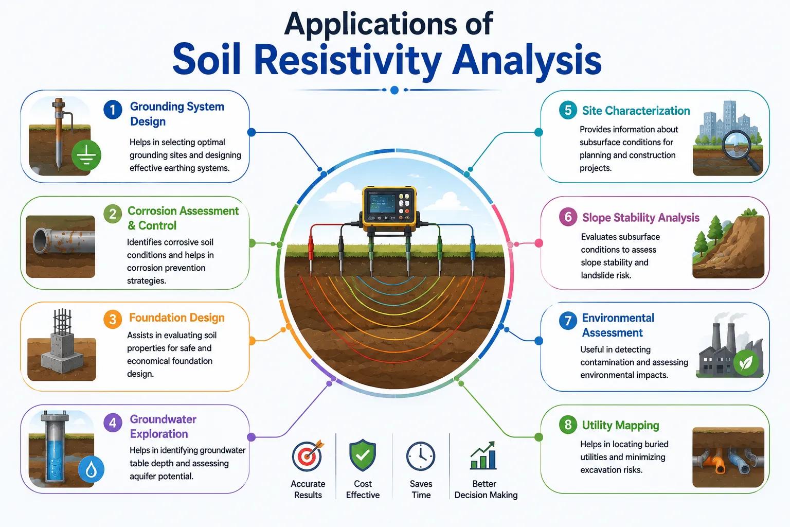
Applications of Soil Resistivity Analysis
Soil resistivity testing is a mandatory pre-design investigation for every electrical infrastructure project requiring a grounding system. Bhoojal Survey provides earth resistivity survey services for the following application sectors across India:
• Solar Power Plants — Earthing Grid Design
• Railway Infrastructure — Traction & Signal Earthing
• Electrical Substations — HV/EHV Grounding Systems
• Airports & Government Infrastructure Projects
• Industrial Facilities — Equipment Protection Earthing
• Commercial & Residential Complex Earthing
• Telecom Towers — Tower Base Earthing
• Wind Farms & Renewable Energy Projects Systems
For each application, Bhoojal Survey delivers a complete soil resistivity investigation report including field measurement data, layered soil model, resistivity depth profile, and engineering recommendations for earthing system design — formatted for direct use by electrical engineers and EPC contractors.
Why Choose Bhoojal Survey for Soil Resistivity Testing Services
Bhoojal Survey is a professional geophysical and electrical investigation consultancy providing soil resistivity testing, earth resistivity surveys, and earthing analysis services across India. Our experienced team combines geophysical measurement expertise with electrical engineering knowledge to deliver resistivity data that your earthing design team can rely on.
- Experienced Geophysical and Electrical Testing Experts: Our field team has conducted Wenner and Schlumberger resistivity surveys for solar plants, substations, telecom towers, and industrial facilities across diverse Indian soil and geological environments.
- Advanced Soil Resistivity Testing Instruments: We deploy precision earth resistance meters and geophysical resistivity instruments calibrated for accurate four-electrode measurement, delivering reliable resistivity data across the full range of Indian soil conditions from high-resistivity rock to conductive coastal clay.
- Accurate Grounding and Earthing Analysis: Every soil resistivity survey is processed to produce a calibrated layered soil model — not just raw resistance numbers — providing the engineered input your earthing system design software requires.
- Fast Reporting and Technical Consultancy: Soil resistivity survey reports are prepared and delivered promptly after field measurement, including field data tables, resistivity depth profiles, layer model parameters, and design-specific recommendations.
- Pan-India Testing Services: Bhoojal Survey provides soil resistivity testing services across all Indian states — from Himalayan foothills to peninsular hard rock, from desert sands to coastal mangrove zones — covering India's full range of soil electrical environments.
- Customised Earthing Investigation Solutions: We design soil resistivity testing programmes precisely matched to your project's earthing standards, site conditions, and electrode configuration requirements — from a single telecom tower site to a multi-bay 400kV substation yard.
Conclusion
Soil resistivity is not a parameter that can be assumed, estimated from soil type tables, or borrowed from a neighbouring site. It must be measured at your project location, at the depths relevant to your earthing system, using recognised geophysical test methods. The investment in a professional soil resistivity survey is small compared to the cost of an earthing system redesign — or the consequences of an earthing failure in a live electrical installation.
Whether your project is a utility-scale solar plant in Rajasthan, a 220kV substation in Maharashtra, a telecom tower network across Bihar, or an industrial facility in Gujarat, Bhoojal Survey's professional soil resistivity testing services provide the ground truth your electrical engineers need to design a
safe, compliant, and reliable grounding system.
Contact Bhoojal Survey for professional soil resistivity testing and earthing analysis services across India.
Frequently Asked Questions (FAQ)
1. What is soil resistivity and why does it matter for earthing systems?
Soil resistivity is a measure of how strongly a soil volume resists the flow of electrical current, expressed in ohm-metres (Ω·m). It directly determines the resistance-to-earth that a grounding electrode achieves in a given soil — low resistivity soils produce low earth resistance (good for earthing), while high resistivity soils require more extensive electrode systems. Soil resistivity data is the primary input for earthing grid design and is required by IS 3043 (BIS), IEEE Standard 80, and CEA regulations for all electrical infrastructure projects.
2. Which method is most commonly used for soil resistivity testing in India?
The Wenner Four-Pin Method is the most widely used technique for soil resistivity testing in electrical infrastructure projects in India and internationally. It involves four equally-spaced electrodes driven in a straight line, with current injected through the outer pair and voltage measured across the inner pair. By varying electrode spacing, a depth profile of soil resistivity is obtained. The Schlumberger method is used for deeper investigations and complex layered soil sites. Both methods are recognised in IS 3043 and IEEE Standard 80.
3. How does soil resistivity affect the design of a solar plant earthing system?
Solar plant earthing grids must achieve a safe earth resistance value — typically below 1 ohm for large utility-scale plants — to protect personnel and equipment during fault events. In high-resistivity soils (such as rocky terrain in Rajasthan or sandy soils in Gujarat), achieving this resistance requires a more extensive buried conductor grid, deeper electrodes, or chemical earthing enhancement. Soil resistivity testing at the plant site provides the layered soil model needed to calculate the required grid dimensions and electrode configuration before construction begins.
4. What is the acceptable soil resistivity range for electrical earthing systems?
There is no single universal acceptable resistivity range — earthing system design adjusts to whatever resistivity the site presents. However, soils with resistivity below 100 Ω·m are generally considered favourable for earthing design, while soils above 1000 Ω·m (typical of rocky, dry, or sandy formations) require special design measures. The goal is achieving the required earth resistance value (as specified in IS 3043 or project specifications) regardless of site resistivity — and soil resistivity testing is what makes the correct design calculation possible.
5. What industries in India require soil resistivity testing services?
Soil resistivity testing is required for all electrical infrastructure projects in India that include earthing systems. Key sectors include solar power plants (utility-scale and rooftop), electrical substations (11kV to 765kV), industrial facilities with HT/LT electrical installations, telecom tower networks, railway traction and signalling systems, airport electrical infrastructure, wind farm earthing systems, data centres, and commercial and residential complexes subject to IS 3043 and CEA earthing regulations.