Soil resistivity test is conducted to measure the resistance of soil when current is passed through it. It is a critical factor in design of systems that rely on passing current through the Earth's surface.
Soil resistivity is the ability of the soil to resist the flow of electricity. Various factors affect the resistivity of a soil such as its composition, temperature and moisture content. Since soil is not a homogenous substance, its resistivity will vary with depth, with lower soil layers having greater moisture content and hence lower resistivity. For hard and rocky soil, the resistivity increases with depth.
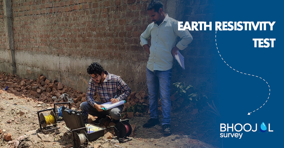
Bhoojal Survey has successfully conducted Soil resistivity test operations at different sites across India using wenner method.
Soil Resistivity Testing has multiple purposes
1. Soil resistivity test is conducted to determine Low resistivity zone for safe earthing purpose
It is most effective way to identify location for passage of excess current to ground by installation of proper grounding systems on basis of resistance offered by soil at a particular location. It is advisable to locate the area of lowest soil resistivity in order to achieve the most economical grounding installation. Wet soil provides low resistivity zone and hard basaltic rocks generally are high resistivity zone.
2. Soil resistivity test using Schlumberger method
It can determine the geological formation of Subsurface and an aid in identifying ore locations, depth to bedrock and other geological phenomena.
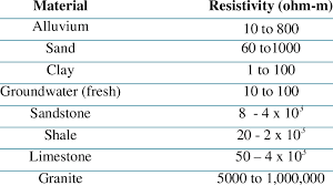
Soil resistivity Chart for materials present at subsurface strata

3. Resistivity Value Indicates Presence of Moisture
Resistivity values affect design of Casing pipe installed beneath earth surfaces. A decrease in resistivity value indicates presence of moisture which leads to corrosion of pipe and leads to failure of piping system due to early aging through rust.
How Soil resistivity test is performed?
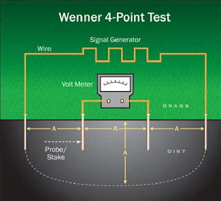
Wenner 4 point test for soil resistivity testing
The Wenner 4-point test method requires driving four spikes into the ground that have been arranged in a straight line and spaced equidistant. A known current is passed between the electrodes placed at the two ends known as the current probes. The potential difference is measured between the two middle spikes which take the soil resistance measurement and are known as the potential probes. Testing is carried out as close to the site as possible.
Instrument required for performing Soil resistivity Testing:

- 1. Soil resistivity meter with battery to generate current
- 2. 4 Electrodes
- 3. Connecting wires (from electrodes to resistivity meter)
- 4. Hammer
- 5. Measuring Tape
Wenner 4 Point methodology
The following step used to test the soil resistivity in this method:
- 1. Placed the soil resistivity measure equipment on the centre of the assessment location.
- 2. Put two potential electrode on the left and right side point of view based on the distance test required. This electrode embedded from 5 to 10 cm to ground, based on the soil condition.
- 3. Put two current electrode on the left and right side point of view based on the distance test required. This electrode embedded from 5 to 10 cm to ground based on the soil condition.
- 4. Connect all electrodes cable with the soil resistivity measuring equipment’s.
- 5. Energize the electrode with the power supply form soil resistance measuring equipment’s.
- 6. Please make sure no one touch the electrode when the electrode energize.
- 7. The value of soil resistivity will calculate and appear on the soil resistivity measuring equipment LCD’s or monitor.
Placement of electrode at equal distance for passing of current through outer electrode and measuring potential difference at inner electrode to determine resistivity of soil
How do I Calculate Soil Resistivity?
The resistance can be measure and resistivity calculated according the following formula.
Where: ρ = Resistivity in Ohm-meter
a = spacing between pin in meter
R = Resistance measurement in Ohm
It should be noted that measurement made in this manner indicate average resistivity over a depth of soil corresponding to the spacing between adjacent pin/electrode.
What is Done During the Testing of Soil Resistivity?
- 1. A site free from interference is chosen.
- 2. Four equally spaced electrodes are driven into the ground.
- 3. A current is injected into the soil using the outer two stakes.
- 4. The potential difference (voltage) is measured between the inner two stakes.
- 5. Data from multiple measurements, at various spacings and directions, is collected.
Soil Resistivity Meter
A soil resistivity meter is the primary instrument used in these tests. It comprises a current generator and a voltmeter and is designed to inject a precise amount of current and accurately measure the resultant voltage.
Data Analysis
Data analysis involves plotting resistivity values against electrode spacing. This assists in deducing the resistivity of different soil layers. Often, a log-log graph is used due to the significant variation in resistivity values.
Shallow Depth Readings vs. Deep Readings
Shallow Depth Readings: These are taken with smaller electrode spacings and provide data about the upper soil layers.
Deep Readings: By increasing electrode spacings, deeper soil layers can be probed, revealing information about their resistivity.
Soil Resistivity Test Location
The location must be representative of the area of interest and free from interference. It should be devoid of large metallic structures or high voltage lines to avoid skewed results.
Soil Corrosivity Testing
A direct offshoot of soil resistivity testing, this determines how corrosive the soil is. Highly resistive soils are usually less corrosive, while low resistivity soils can cause increased rates of metal corrosion.
How Bhoojal Survey can help in Soil Resistivity Testing
Bhoojal Survey Company excels in Soil Resistivity Testing, providing comprehensive services to determine the electrical resistivity of soil. Our expert team employs state-of-the-art equipment and industry-best practices to accurately assess soil properties.
We offer detailed analysis and consultation, assisting clients in understanding soil resistivity's crucial role in grounding systems for various applications, such as electrical substations and lightning protection.
With Bhoojal's expertise, clients can optimize grounding designs, ensure safety, and enhance system performance. Our commitment to precision and quality makes them a trusted partner in managing soil resistivity challenges for industries, infrastructure, and commercial projects.
FAQs: Soil Resistivity Test
Why do we test soil resistivity?
To understand the electrical characteristics of the ground, which impacts grounding designs, corrosion potential, and various engineering projects.
Why Determine the Soil Resistivity?
It aids in optimising the design of earthing systems, assessing corrosion risks, and studying soil layer structures.
What is the meaning of resistivity test?
A resistivity test measures how strongly a given material opposes the flow of electric current. In this context, we're studying the soil's ability to resist electrical flow.
What is the soil resistivity test formula?
The formula of soil resistivity is ρ=2πaV/I
What is the soil resistivity test for earthing?
It helps in designing an efficient grounding system that ensures electrical safety and equipment protection.
Download Soil Resistivity Test Meaning, Procedure and Report PDF
